How 868 MHz Antenna Sizing and Ground Plane Affect Link Budget in Real Deployments
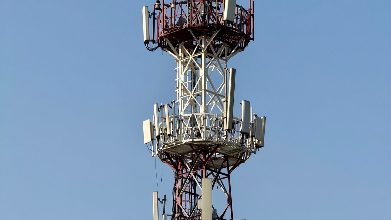
The physics of 868 MHz antennas are well-understood, but the translation from physics to real-world performance involves a set of practical considerations that don’t always make it into the conversation when hardware is being selected. Wavelength determines antenna dimensions, and those dimensions interact with mounting geometry, ground plane size, and nearby structures in ways that can shift the effective gain of a deployed antenna by several decibels in either direction from its datasheet specification.
For LoRa and other LPWAN applications operating in the 868 MHz European sub-GHz band, this variation matters because the link budgets for these systems are already working hard — the appeal of 868 MHz IoT is the ability to cover large areas with low transmit power, and that leaves little margin for antenna performance shortfalls that weren’t anticipated.
Wavelength and Physical Antenna Dimensions
At 868 MHz, the free-space wavelength is approximately 345 mm. A quarter-wave monopole antenna — the simplest and most common form for IoT sensor nodes — is roughly 86 mm long. A half-wave dipole is about 172 mm. These dimensions determine the antenna’s self-resonance and feed point impedance, and deviations from them require matching networks that add complexity and loss.
This is a relevant consideration for compact sensor node designs where the antenna has to fit into a constrained form factor. Shortening the antenna element below its natural resonant length reduces radiation efficiency — the antenna presents a reactive impedance to the transmitter, the matching network dissipates some power, and the overall radiated power is less than the transmitter’s output would suggest. The loss from a poorly matched short antenna can easily reach 3 to 5 dB, which is equivalent to cutting transmitter power by half to a quarter.
868 MHz sits in a frequency range where this trade-off is more manageable than at higher frequencies — the natural antenna dimensions are small enough to accommodate in most outdoor IoT enclosures without heroic miniaturization. Designs that don’t need to be tiny are better served by an antenna sized for actual resonance than by a miniaturized solution that pays an efficiency penalty.
Ground Plane Effects on Monopole Antennas
A monopole antenna requires a ground plane to function. The ground plane acts as the electrical mirror image of the antenna element — the two together behave like a dipole from an RF standpoint. The size and quality of the ground plane directly affects the radiation pattern and efficiency.
For a quarter-wave monopole at 868 MHz, the ground plane should extend at least a quarter-wavelength in radius from the antenna base — about 86 mm — to approach the performance of a reference dipole. Larger ground planes improve low-angle radiation (important for long-range terrestrial links) and reduce the sensitivity of the pattern to what’s nearby.
In practice, the ground plane for most IoT sensor nodes is the PCB, the metal enclosure, or whatever mounting structure the antenna is attached to. A small PCB with limited copper area, a plastic enclosure with a small metal mounting plate, or an antenna mounted on a plastic pole with no significant metal nearby — all of these provide undersized ground planes that degrade monopole performance.
This degradation isn’t uniform — it shifts the radiation pattern, often tilting maximum radiation upward (toward the sky) rather than toward the horizon where the gateway is. For a gateway that’s at the same elevation or lower than the sensor node, this pattern tilt reduces effective link gain even if the antenna’s total radiated power is acceptable.
A proper 868 mhz antenna designed for outdoor mast mounting typically includes an integral ground plane or is specified for mounting on a metal pole that serves as the ground plane. This mounting configuration produces the radiation pattern the datasheet describes. Mounting the same antenna on a small plastic bracket or routing it inside a non-metallic enclosure changes the performance in ways the datasheet doesn’t capture.
Nearby Structure Effects
The 86 mm quarter-wave dimension at 868 MHz means that structures within roughly one wavelength (345 mm) of the antenna can couple with it electrically, altering its impedance and radiation pattern. This is a shorter interaction distance than at lower frequencies like 433 MHz, but still long enough to include most enclosure walls, cable runs, and mounting hardware within practical installation geometries.
Metal within this coupling distance doesn’t always reduce performance — a metal mounting pole acting as a counterpoise ground plane can actually improve monopole antenna performance compared to a floating installation. The effect depends on the geometry, the dimensions of the metallic structure relative to wavelength, and how the antenna is oriented relative to the structure.
What consistently degrades performance is cable routing parallel and adjacent to the antenna element for more than a few centimeters. The coaxial cable from the radio to the antenna, if it runs parallel to the antenna element rather than exiting perpendicular to it, becomes a parasitic radiator that distorts the antenna pattern and can detune the antenna’s resonance. The cable should exit the antenna feedpoint perpendicular to the antenna axis — typically downward for a vertically oriented whip — and maintain that perpendicular routing for at least a wavelength before bending or routing in other directions.
Link Budget Consequences
The cumulative effect of ground plane undersize, nearby structure coupling, and cable routing issues can realistically account for 3 to 6 dB of effective gain reduction compared to what a datasheet specification would predict. In a 868 MHz LoRa link budget, 6 dB corresponds to roughly halving the reliable communication range.
Quantifying these effects before deployment requires either field measurement at a representative test site or simulation, neither of which happens routinely for volume IoT sensor deployments. The alternative is building in margin at the design stage — oversizing the ground plane where possible, using external antennas with defined mounting geometry rather than embedded PCB antennas, and validating range in the actual deployment environment before committing to a large-scale rollout.
Range validation in the deployment environment is not a substitute for understanding the physics, but it catches the installation-specific effects that physics-based calculation alone can’t predict. A sensor node design that achieves its specified range in lab conditions but doesn’t validate in the field has gap that’s worth understanding before it’s replicated across hundreds of installed units.